ArticlePosted on September 2013
Creating a Spherical Environment Mapping shader
Reading time: 10 minutes
Topics: WebGL, GLSL, three.js, matcap
This is a legacy post, ported from the old system:
Images might be too
low quality, code might be outdated, and some links might not work.

One of the most important aspects of computer-generated images is lighting. It takes a lot of calculations, setup and tweaking to get surfaces to look realistic and convincing.
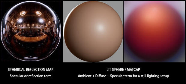
Spherical reflection (or environment) mapping (SEM) is a fast way to fake the specular term of the lighting equation, and for specific cases, to fake lighting altogether. This technique has been popularised by software like Pixologic ZBrush or Luxology Modo.
LitSphere/MatCap texture maps
SEM uses special texture maps called “lit spheres” or “matcaps”. These are essentially spherical reflection maps, but with a more diffuse colour instead of a sharp image. The sphere map contains everything that is in front of the camera, which means that the texture contains the incoming light inciding in the surface facing the camera. That’s why it doesn’t work as a perfect environment map: it doesn’t rotate with the view because it’s missing part of the information. All we can emulate is an object rotating by itself in a still light and camera setup.
Setting up the shader
The main idea of SEM is to get the UV coordinates (which are used to lookup the matCap texture) from the normal vector on the fragment instead of the original texture coordinates from the object. That can be done in the vertex shader -and let the GPU take care of the interpolation- or in the fragment shader. We'll do the per-vertex version first.
In order to understand SEM spatially, assume that surfaces looking straight into the camera (the normal vector is parallel to the camera vector) is mapped to the texel right in the middle of the matCap texture; and as the normal vector diverges from the camera vector (the angle between both vectors tends to 90º) the texel is looked up more towards the borders. Normals looking upwards (we're talking screen space so "up" is towards the physical top of the screen) are mapped to the top of the matCap texture; normals looking downwards, to the bottom. Same with left and right.
So first we need to set up two vectors, e (Eye) and n (Normal). Eye is the vector that goes from the camera (a point in space at the origin) to the fragment position. Normal is the normal in screen space. We need to convert the 3-dimensional position into a 4-dimensional vector to be able to multiply it by the matrices.
Once we have both vectors, we calculate the reflected vector.
This tutorial is based on the GLSL language to code the shader. If you're targeting a different shading language and don't have the reflect() function, you can replace it with the equivalent expression r = e - 2. * dot( n, e ) * n;
Then we take that vector, and apply the formula to get the UV tuple.
Here's the vertex shader code:
SEM shader, per-vertex
GLSL - Vertex shader
varying vec2 vN;

void main() {

  vec4 p = vec4( position, 1. );

  vec3 e = normalize( vec3( modelViewMatrix * p ) );
  vec3 n = normalize( normalMatrix * normal );

  vec3 r = reflect( e, n );
  float m = 2. * sqrt(
    pow( r.x, 2. ) +
    pow( r.y, 2. ) +
    pow( r.z + 1., 2. )
  );
  vN = r.xy / m + .5;

  gl_Position = projectionMatrix * modelViewMatrix * p;

}
The fragment shader just takes the GPU-interpolated values for the UV tuple, and use it to lookup in the matCap texture. Here's the code:
SEM shader, per-vertex
GLSL - Fragment shader
uniform sampler2D tMatCap;

varying vec2 vN;

void main() {

  vec3 base = texture2D( tMatCap, vN ).rgb;
  gl_FragColor = vec4( base, 1. );

}
Here's the JavaScript code to create the shader material with three.js. Basically instantiate a new THREE.ShaderMaterial, specifying the vertex shader and fragment shader scripts, and a uniform that is a texture with the matCap map. Just in case, set the horizontal and vertical wrapping of the texture to clamp, so it doesn't wrap around. Here's the code:
Creating THREE.js material
JavaScript - index.html
var material = new THREE.ShaderMaterial( {

  uniforms: {
    tMatCap: {
      type: 't',
      value: THREE.ImageUtils.loadTexture( 'matcap.jpg' )
    },
  },
  vertexShader: document.getElementById( 'sem-vs' ).textContent,
  fragmentShader: document.getElementById( 'sem-fs' ).textContent,
  shading: THREE.SmoothShading

} );

material.uniforms.tMatCap.value.wrapS =
material.uniforms.tMatCap.value.wrapT =
THREE.ClampToEdgeWrapping;
And the material is ready to be assigned to an object!
Assigning the material to an object
A material using SEM is very useful to highlight variations in the mesh: creases, bumps, even slow ondulations. It doesn't work that well on a cube, for instance. And does absolutely nothing on a sphere: SEM on a sphere is exactly the same as a planar projection of the matCap texture. Use a good old Torus Knot geometry to test the shader.
Also, you might be interested in Creating a disorted sphere with Perlin Noise
Phong (per-fragment) shading
I don't think it's truly necessary, but maybe -depending on the model you're rendering, specially if it's too low-poly- you might need to perform the calculations per-fragment, instead of relying on the GPU-interpolated value. Here's the same vertex shader modified to use a per-fragment calculation:
SEM shader, per-fragment
GLSL - vertex shader
varying vec3 e;
varying vec3 n;

void main() {

  e = normalize( vec3( modelViewMatrix * vec4( position, 1.0 ) ) );
  n = normalize( normalMatrix * normal );

  gl_Position = projectionMatrix * modelViewMatrix * vec4( position, 1. );

}
Notice that we don't calculate the tuple vN and pass it in a varying, but instead pass the e (Eye) and n (Normal) values to the fragment shader. Here's the fragment shader code:
SEM shader, per-fragment
GLSL - fragment shader
uniform sampler2D tMatCap;

varying vec3 e;
varying vec3 n;

void main() {

  vec3 r = reflect( e, n );
  float m = 2. * sqrt( pow( r.x, 2. ) + pow( r.y, 2. ) + pow( r.z + 1., 2. ) );
  vec2 vN = r.xy / m + .5;

  vec3 base = texture2D( tMatCap, vN ).rgb;

  gl_FragColor = vec4( base, 1. );

}
So the reflection and vN calculation that was previously done per vertex and interpolated across the fragments is now calculated for every single fragment.
Demo
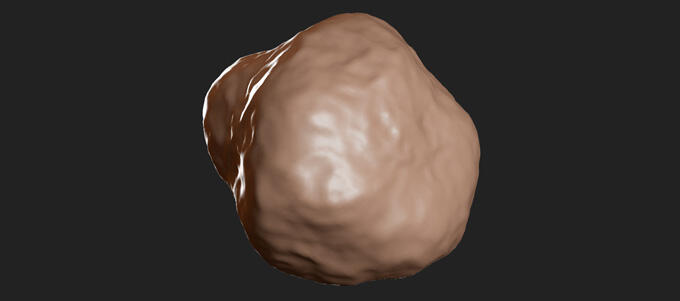
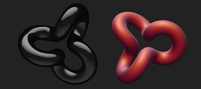
The demo shows three different materials (Matte red, Shiny black and Skin) that can be used on three different models (Torus Knot, Blob and Suzanne). The materials are exactly the same, the only thing that changes is the matCap texture, but it shows the amazing power of the technique, making objects look completely different.
Toggle the "Enable Phong (per-pixel) shading" flag to see the difference between per-vertex and per-fragment calculations. The most notable difference is on the edges of the objects.
Torus Knot is a THREE.TorusKnotGeometry from the default set of geometries of three.js. Blob is a THREE.IcosahedronGeometry with the vertices disturbed based on a Perlin noise function (a mix of standard noise and crinkly noise). Suzanne is the ubiquous Blender mascot, processed with THREE.SubdivisionModifier to get a smoother model.
It works on Chrome, Firefox, Safari for OSX, Windows and Linux. It also works on Chrome and Firefox for Android. Try it on a mobile phone, it's got touch events support!
Conclusion
That's basically it, as you can see there is nothing terribly mysterious about SEM. The secret is in using good models and good matCap maps. Google image search, a good image editing softare or -even better- a good graphician are the best tools!
Further things to try with this technique: creating the matCap texture on a previous step with a shader; combining several maps to simulate influence from different light sources; or trying to do the same but using the matCap as normal map, and see what happens.